Re-Wiring the Odyssea MH unit!
When it came time to move to the Metal Halide lights, I wasn't sure what kind to get. I wanted them to be easy to install, and attractive. I don't have a hood, and needed the lights to look nice while exposed. So I got the Odyssea because, A) cost, and B) cost.
It has 2 MH lights, 2 CF Actinic lights and a row of little blue LED moonlights. However, the first flaw is apparent when you try to hook them up to timers. The MH and Moonlights are on the same plug/ballast. So you could have them both on, or both off.. OR just turn them on and off manually. Heh. Of course I didn't know any of this when I bought the unit.
So I decided to rewire it. After all how hard could it be? The answer is, not hard at all! Now I have no prior electrical experience, and was able to pull this off.
I found some directions online here: from someone who had already done it.
The Post where I found the original directions.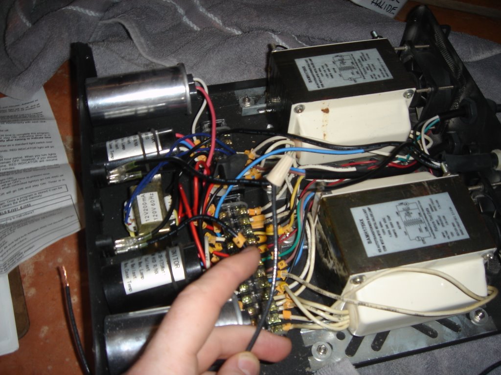 My experience was different than the directions because he di
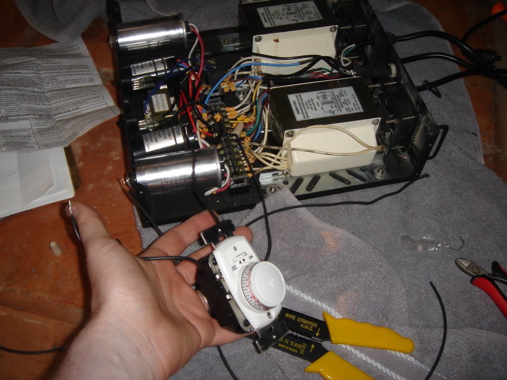 didn't say anything about switches.
But basically, I found the cable leading from the plug to the switch, and spliced in the timer there.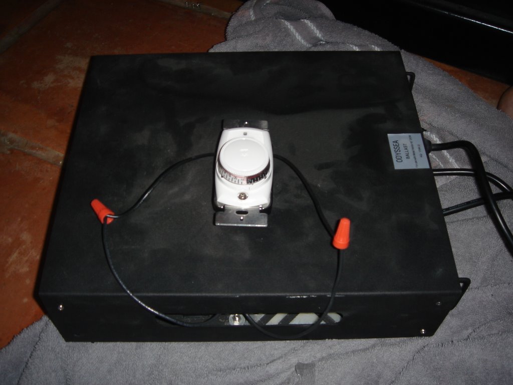
I found that the timer doesn't work with the LED lights. I have no explanation. It just didn't.
However, it works great with the MH,and really, that's the only one you need to fix anyway. The Actinic were on another ballast altogether and could be set on a separate timer.
So here it is after it in installed into the circuit. It sure looks intimidating doesn't it? But it was easy, and as long as you remember to unplug it, it's safe.
Now aesthetically, it's not the best solution. But I figured since it's just going to sit under the cabinet, why does it need to look good? So I just set it ontop of the case of the ballast. I run the wires out of one of the vents on the side.
Here the unit is all put back together, and the timer just sitting up there.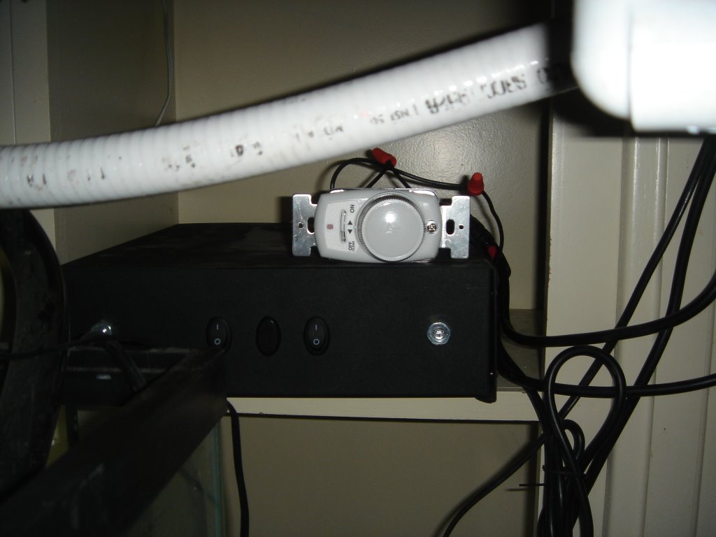
I suppose I could get a switch box, and mount it to the ballast case.. But honestly, I probably won't.
It's working, and now I have Actinic's coming on at 12:30, the MH's coming on a 1pm, and going off at 10pm, and the Actinics going off at 10:30.. With the Moonlights on all the time.
One thing I also noticed while doing this is that the fans for the MH's had burned out. I have no idea how long they had been out, but they were. So I went up to fry's and tried to replace them. They were 40x40 12v DC fans.. but Fry's was all out. So I bought one 80X80 12v DC fan and jammed it in there. It works good, and is 100% silent. Big change over the default fans. So if you have noisy ones they are easy and cheap to replace. And new ones will be silent.
Next I'll show off the chiller. I am shopping for that now. If you have a 1/8 HP chiller for under $500 I'll buy it.. but hurry, I'm going up to the LFS tomorrow to pick up one for $545.
So look forward to that!
...Instead of wiring an extra plug for each switch, I spliced in timers in series for each circuit. This left only one plug for the entire ballast to plug in and left me with timer control of each lighting circuit independant from each other.
Here's the list of parts (from any hardware store): 16 gauge stranded wire(easier to work with in the small space), 6 wire nuts for 16 gauge wire, and 3 Intermatic wall switch timers.
WARNING - unplug the ballast box before doing any of this work.
First, prewire (for series as per the timer directions) and mount the timers in a seperate box. Be sure to label each set of wires for it's respective switch.
Second, unplug and open the ballast. Locate the white wire coming from the plug and follow it to the fuse. Coming out of the fuse will be two black wires.
Follow one, it will go to #9 on the terminal board. This will be the circuit for the MH, cut this wire (not too close to the terminal board) and splice in the timer using the wire nuts. One splice from the ballast box to the timer, another from the timer to the ballast box. It's just like repacing a wall switch.
Follow the other and you will come to a splice with two more wires.
Follow one of these to #5 on the terminal board. This is the circuit for the CF. Cut this wire and splice in the timer as above.
Follow the other one to #6 on the terminal board. This is for the moonlight. Again cut and splice in the timer as above.
You're now wired! Close up the box. I ran my wiring through the side vents of the case to prevent pinching or crimping any wires while closing up the box. This has been working very well for me and I hope it helps others.
posted by kungfukoi at
3:37 PM
![]()


0 Comments:
Post a Comment
<< Home